Ra100z Wiring Diagram
Installing the InnovairFlex Sampling Tube The InnovairFlex sampling tube may be installed from the front or back of the detector. GENERAL INFORMATION The National Fire Protection Association has published codes standards and.

Fire Alarm Wiring Diagram Fire Alarm Fire Protection System Wiring Diagram
System Sensor is a global manufacturer of fire and life safety devices in smoke detection carbon monoxide detection and notification technology.
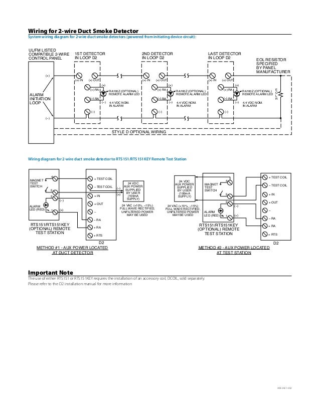
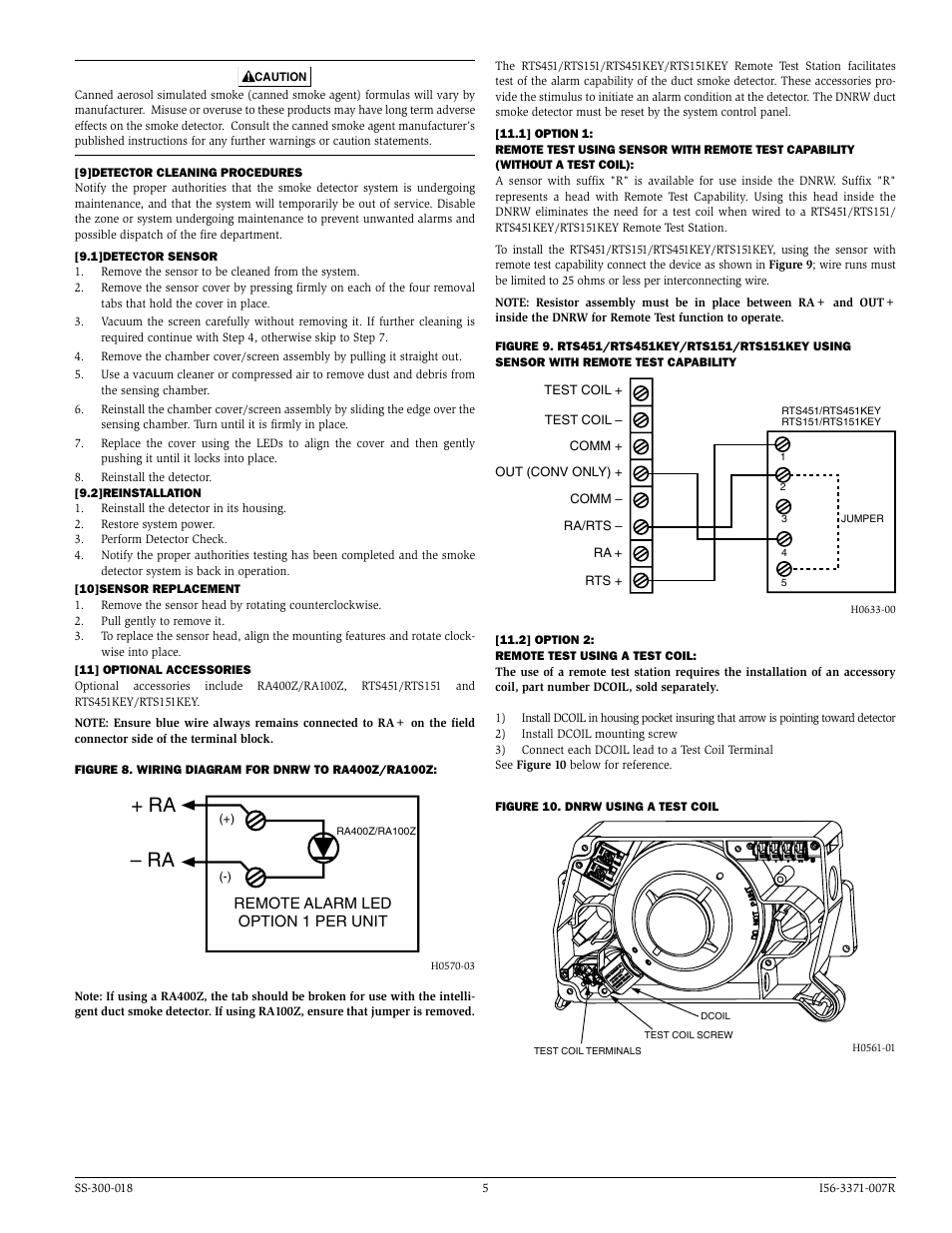
Ra100z wiring diagram. GENERAL INfORMATION The National Fire Protection Association has published codes standards. Ra100z 2w-b or 2wt-b ra100z eol resistor s0133-01 figure 3b. RA100Z Remote annunciator alarm LED DST3 Metal sampling tube duct widths 2 ft to 4 ft 06 to 12 m RTS151 Remote test station DST5 Metal sampling tube duct widths 4 ft to 8 ft 12 to 24 m RTS151KEY Remote test station with key lock.
The RTS151 and RTS151KEY remote test stations are automatic fire detector accessories designed to test duct smoke detectors from a convenient location. For information about SGX-32 stations in custom. Figure 1 Figure.
RTS151KEY 12 mA 12 mA Max. RTS151RTS151KEY JUMPER 4 5 3 2 1 TEST COIL TEST COIL COMM OUT CONV ONLY COMM RARTS RA RTS Wiring for Intelligent Non-Relay Duct Smoke Detector COMM. RA100Z The remote annunciator is connected between terminals 1 and 3 using the spade lug terminal packed with the remote annunciator.
Installing the InnovairFlex Sampling Tube. RTS151 RTS151KEYA 0 mA 12 mA. Charles Illinois 60174 1-800-SENSOR2 FAX.
Figure 3 illustrates the front locking tab. 21 DETECTOR fEATURE SET Utilizes plug-in head part number SD355R Sampling tubes install from front and rear Compatible with existing accessories. Figure 5 illustrates the wiring diagram for 2-wire duct smoke detector to the RTS151RTS151KEY.
3825 Ohio Avenue St. RA100Z 0 mA 12 mA Max. The spade lug termi-.
Wiring Diagrams Ordering Information SGX-32SK2 Single Action Explosion-Proof Manual Alarm Station SGX-32SK1 Dual Action Explosion-Proof Manual Alarm Station SG-GR01 Scored acrylic plastic breakrods 1 dozen to a package Note. TYPICAL WIRING DIAGRAM FOR 2-WIRE LOOP - ULULC Listed Compatible Control Panel CAUTION. Such as the RA400ZRA100Z remote LED annunciator as well as remote test ca-pability with the RTS451151 or RTS451KEYRTS151KEY Remote Test Stations.
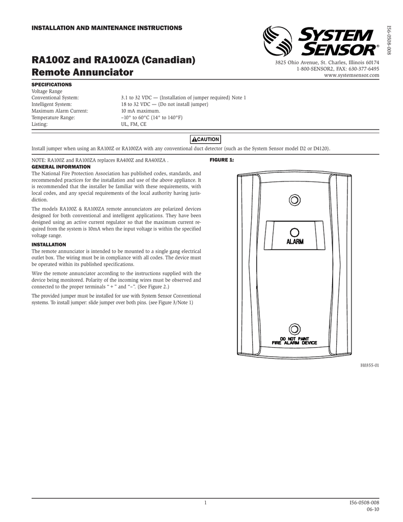
Potter Electric Signal Company FIRE ALARM EQUIPMENT XXXX. RA100Z Remote Annunciator A variety of accessories are available including remote test stations and several different means of visible and audible system annunciation. RA100Z and RA100ZA Canadian Remote Annunciator INSTALLATION AND MAINTENANCE INSTRUCTIONS 3825 Ohio Avenue St.
RA100Z and RA100ZA replaces RA400Z and RA400ZA. Do NOT use the tamper-resistant capability if the XR2 or XR2B Removal Tool will be used. Set the desired address on.
The tube locks securely into place and can. Do not loop wire under terminal 1 or 2. Wiring diagram for 2-wire duct smoke detector to RTS151RTS151KEY Remote Test Station.
It is intended for use with System Sensor 4-wire conventi onal duct smoke detector applications without a system control panel to comply with NFPA 90A. They have been designed using an active current regulator so that the maximum current required from the system is 10mA when the input voltage is within the specified voltage range. A sensor that fails any of these tests should be cleaned as described under CLEANWire the sensor base supplied separately per the wiring diagram see Figure 1.
The tube locks securely into place and can be removed by releasing the front or rear locking tab. LINE ULFM LISTED CONTROL PANEL 1ST DETECTOR IN LOOP 2ND DETECTOR IN LOOP COMM. LINE ULFM LISTED CONTROL DETECT PANEL 1ST OR IN LOOP 2ND DETECTOR IN LOOP COMM.
System wiring diagram for DNR. Charles IL 60174 Phone. RTS151KEY 12 mA 12 mA Max.
RA100Z 0 mA 12 mA Max. Each station is supplied with one acrylic plastic breakrod and key. RA100Z and RA100ZA replaces RA400Z and RA400ZA.
RA100Z 0 mA 12 mA Max. RTS151RTS151KEY 0 mA 12 mA Max. C 819 Figure 10.
The APA151 piezo annunciator which replaces the APA451 with a new improved look provides an audible alarm signal a red LED to indicate alarm status and a green LED to indicate power status. Wiring diagram 4w-b and 4wt-b aux or smoke power idc 4-wire control. RTS151 0 mA 12 mA Max.
RA100Z and RA100ZA Canadian Remote Annunciator INSTALLATION AND MAINTENANCE INSTRUCTIONS 6581 Kitimat Road Unit 6 Mississauga Ontario L5N-3T5 1-800-SENSOR2 FAX. The RA100Z and RA100ZA remote annunciators are designed for both conventional and intelligent applications. RTS151 0 mA 12 mA Max.
Typical Wiring Diagram for 2-wire loop TAMPER-RESISTANCE Note. The red LED provides visual indication of an alarm condi-tion. The Tamper Resistant Tab in the Detector Mounting Bracket can make the detector tamper-resistant by making it nec-.
Installing the InnovairFlex Sampling Tube The InnovairFlex sampling tube may be installed from the front or back of the detector. Installing the InnovairFlex Sampling Tube DNRA Wiring Diagram Accessory Current Loads 24 VDC Device Standby Alarm RA100ZA 0 mA 12 mA Max. System wiring diagram for 2-wire duct smoke detectors powered from initiating device circuit.
The System Sensor RA100Z remote annunciators are polarized devices designed for both conventional and intelligent applications. All wiring must conform to applicable local codes ordinances and regulations. Nohmi Protocol Example of SLC Wired Class A Address No.
Wiring Diagram-- AFC Series SLC Loop Class B Wiring Diagram- 10 AFC-100 INS ALLATION MANUAL-5403648-RE. RTS151RTS151KEY JUMPER 4 5 3 2 1 TEST COIL TEST COIL COMM OUT CONV ONLY COMM RARTS RA RTS Wiring for Intelligent Non-Relay Duct Smoke Detector COMM. Nohmi Protocol Example of SLC Wired Class X Figure 11.
System wiring diagram for DNR. Break wire run to.
Https Co Kitsap Wa Smartgovcommunity Com Blob D0bf4ea0 B159 4fb9 9241 Da017e6c22b1
Ra100z And Ra100za Canadian Remote Annunciator
B501aus Installation Manual Electrical Wiring Manufactured Goods

System Sensor Ra100z Duct Smoke Detector Accessories Remote Led

Home Theater Speaker Wiring Diagram Wiring Diagram Access Control System Security Camera Wiring Diagram

How Do I Wire A 2w B Alarm Grid

How Do I Wire A 2w B Alarm Grid

10 Case Ih Cx100 Engine Wiring Diagram Engine Diagram Wiring Diagram Alternator
Https Www Gamewell Fci Com Catalogdocuments 9021 60476 Pdf
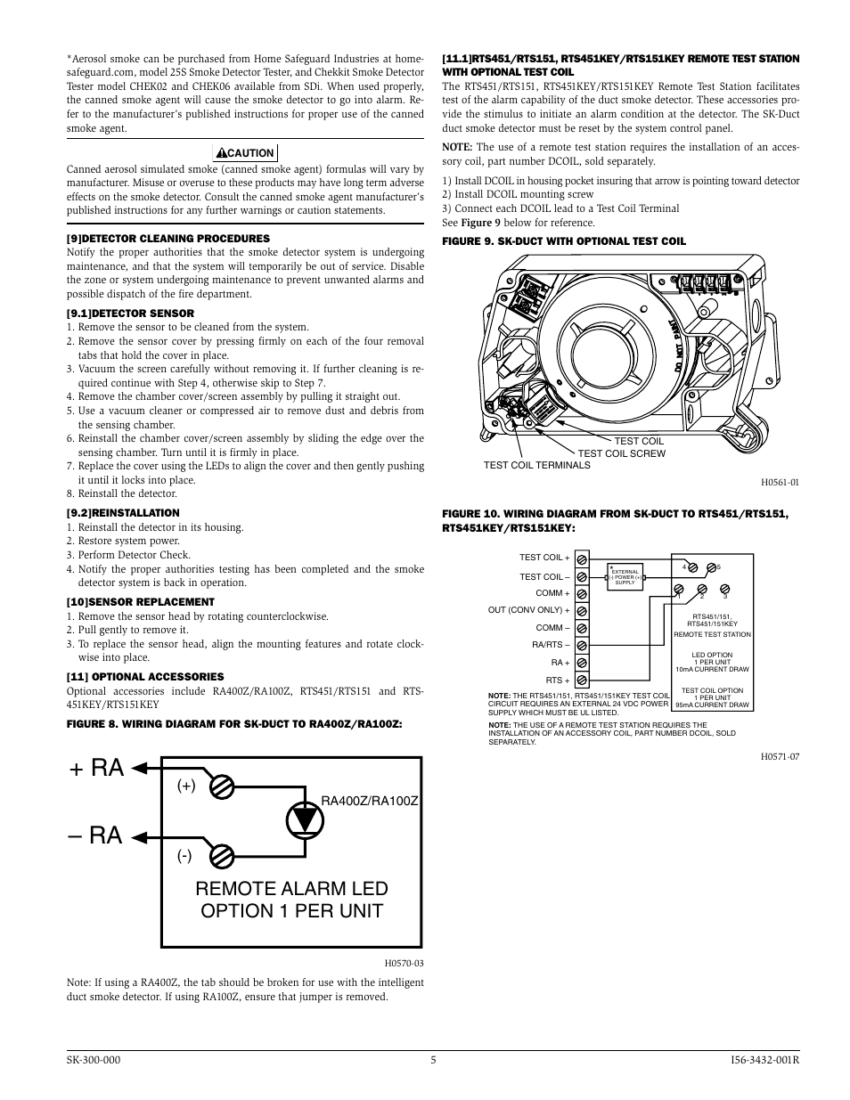
Ra Ra Remote Alarm Led Option 1 Per Unit Silentknight Sk Duct Addressable Photoelectric Duct Detector User Manual Page 5 6
Https Www Gamewell Fci Com Catalogdocuments 9021 60476 Pdf
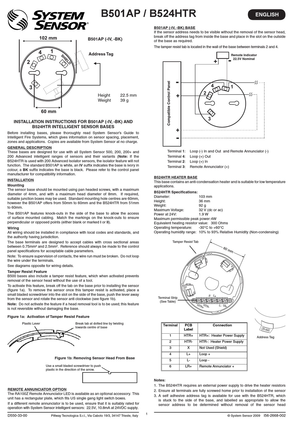
System Sensor B501ap Iv Installation Instructions Pdf Download Manualslib
Http Files Pranakorntech Com Honeywell Honeywell 20morley Honeywell 20morley 20ul Manual 20morley 20ul Ns Sh 0005 Slc Wiring Manual 091905 Pdf
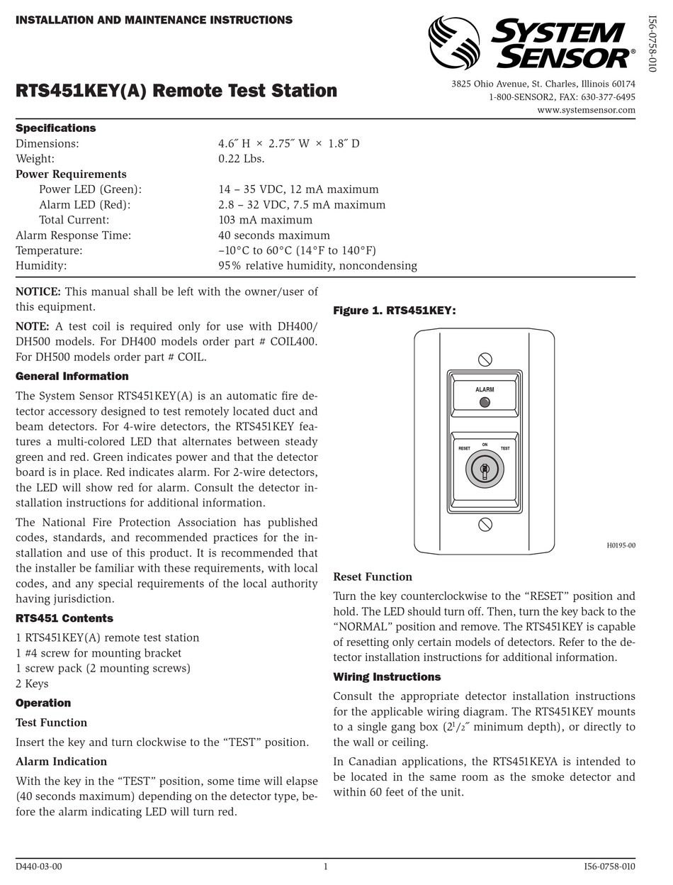
System Sensor Rts451key Installation And Maintenance Instructions Pdf Download Manualslib
