18 Pulse Vfd Wiring Diagram
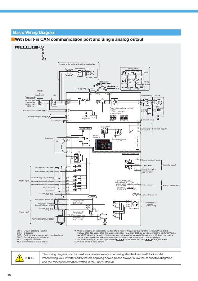
The VFD main circuit terminals shown as below Figure. This type of converter is called a six-pulse design because it draws current in six distinct pulses from the AC line.
Diagram 2004 Arctic Cat 400 Wiring Diagram Full Version Hd Quality Wiring Diagram Diagramrt Teatrodelloppresso It
Multi-pulse VFDs are those VFDs whose line converters rectifiers converting the ac input voltage to dc to feed the inverter are configured with the input phase-shifting transformer to produce a smoother dc link voltage.

18 pulse vfd wiring diagram. Wiring and Grounding Guidelines for Pulse Width. One and one y. A typical diagram of a series connected eighteen pulse drive constructed from a standard six - pulse drive two external rectifiers and a conventional 18 pulse isolation transformer appears in figure 1.
18 -- Typical Wiring Diagram -- Single Package Rooftop Unit 48HC SRT with VFD shown 4850HC. Overcurrent Protection for 3-Wire Control Circuits 11 AC. Vfd wiring diagram.
Call 800-800-2261 to schedule your appointment with a field engineerLearn the basic wiring of variable frequency drives VFD with our el. The drive has terminals available to connect a DC link choke. The CPX series of variable frequency drives uses advanced 18-pulse clean power technology that significantly reduces line harmonics at the drive input terminalsresulting in one of the purest sinusoidal waveforms available.
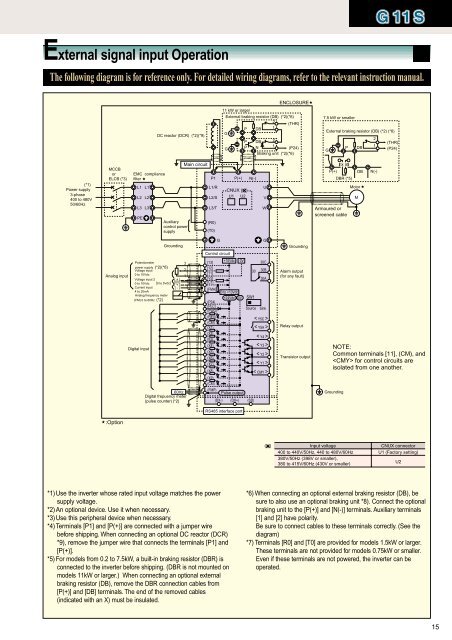
C-1 Guidelines on standard RS485 wiring practices added. Because the current draw is not a smooth sinus waveform this non. 41 Main circuit wiring diagram Figure 4-1 Main circuit wiring RL1 SL2 T M U V W PE Circuit VFD A C p o w e r 42 Main Circuit Terminals Diagram Apply to Main circuit terminal Terminal name Function 220V 1-phase 04KW55KW L1L2 220V 1-phase Input terminals UVW 220V 13-phase Output terminals E Earthing 220V 1-phase 75KW15KW.
We strongly recommend using a certified electrician to set up your vfds. 1 The VFDs three phase AC input terminals rl1 sl2 tl3 The power lines input terminals connect to 3 phase AC power through line protection or leakage protection breaker it does not need to consider the connection of phase sequence. Learn the basic wiring of variable frequency drives vfd with our electrician steve quist.
The main purpose of the 12 diode and 18 diode arrangements are to achieve lower harmonic distortion on the line side. Assortment of vfd wiring diagram. Summary of Changes This manual contains new and updated information as indicated in the following table.
They prevent upstream transformer overheating and overloading enabling the application of generators and other high-impedance systems. But we cannot start the vfd like normal starter. Single Phase Variable Frequency Drive VFD Circuit.
Some communication protocols have their own cabling standard that should be followed. 1-18 Description for option 21 of parameter t221 Relay Out Sel corrected. This manual provides basic information to install protect wire and ground pulse-width modulated PWM AC drives.
18 and 24-pulse vfd 18 and 24-pulse VFDs form 18 and 24-pulse rectifiers by con-. The pulse number relates to the number of ripples in the dc link voltage in one cycle of the ac input voltage. These rectifiers are fed through a transformer with two secondary windings.
This manual is intended for qualified personnel who plan and design installations of PWM AC drives. Danfoss fc-51 vfd drive startstop with pulse wiring overview Instructions-For start No terminal -18For stop Nc terminal -27For com use terminal -12For. 12-pulse VFDs as shown in figure 2 consists of 12-pulse rectifier formed by connecting two six-pulse rectifiers in parallel to feed the same dc bus voltage.
S tandard twisted pair cables will provide protection for EMI but it is suggested to use a shielded twisted pair cable. Wiring Diagram Book A1 15 B1 B2 16 18 B3 A2 B1 B3 15 Supply voltage 16 18 L M H 2 Levels B2 L1 F U 1 460 V F U 2 L2 L3 GND H1 H3 H2 H4 F U 3 X1A F U 4 F U 5 X2A R Power On Optional X1 X2115 V 230 V H1 H3 H2 H4 Optional Connection. - Wiring - Follow local codes for wiring.
Figure C1 Network Wiring Diagram updated. As channel three of the PLC card is connected to 89 Page 8 column 9 we should turn to page 8 column 9 to see the rest of the wiring diagram. These terminals are used.
Nu m b e r. Of course its not possible without a VFD Variable Frequency Drive in between the motor and the PLC card. Requirements 14 AWG 600V MTW Stranded for 120Vac wire and 16 or 18 AWG 600V MTW Stranded wire for 24Vdc wire for up to 10 and 5 amps.
IMPULSEG VG Series 4 Instruction Manual - February 2017 ii DANGER WARNING CAUTION and NOTE Statements DANGER WARNING CAUTION and Note statements are used throughout this manual to emphasize important and critical information. The block diagram below shows a typical vfd installation. Understandably the higher order arrangements take up more space and cost more.
The 12 pulse would be made up of 2 sets of 6 pulse rectifiers supplying the DC bus in parallel and the 18 pulse with 3 sets of 6 pulse rectifiers. For the Variable Frequency Drive VFD factory-installed option. They do NOT draw current continuously but in the case of a VFD only when the incoming line voltage exceeds the drives DC bus voltage or in the case of a DC drive only when the SCR in the converter is gated on.

Diagram 2006 Lincoln Navigator Wiring Diagram Full Version Hd Quality Wiring Diagram Diagrammd Prolococusanese It

Single Phase Variable Frequency Drive Vfd Circuit Circuit Diagram Power Inverter Circuit Diagram Electronic Circuit Projects

Schematic Representation Of A Traditional 18 Pulse Converter Circuit Download Scientific Diagram

Schematic Representation Of A Traditional 18 Pulse Converter Circuit Download Scientific Diagram
Diagram Smart Board Wiring Diagram Full Version Hd Quality Wiring Diagram Diagramman Prolococusanese It

1982 Jeep Cj5 Wiring Diagram Jeep Cj5 Jeep Jeep Cj7

18 96 Civic Engine Wiring Diagram Engine Diagram Wiringg Net Honda Civic Honda Diagram

How Do I Wire Up A 2pin Blinker Can In 2021 Wiring Diagram Motorcycle Wiring Relay

Diagram Four Winns Wiring Diagram Full Version Hd Quality Wiring Diagram Diagramman Prolococusanese It

Diagram 99 Intrigue Wiring Diagram Full Version Hd Quality Wiring Diagram Diagramman Prolococusanese It
Diagram Ahu Wiring Diagram Full Version Hd Quality Wiring Diagram Diagramman Prolococusanese It

Pdf A Variable Frequency Drive Trainer For Use In An Agricultural Electricity Course

Electronicsstore Electrical Circuit Diagram Electronics Projects Interface

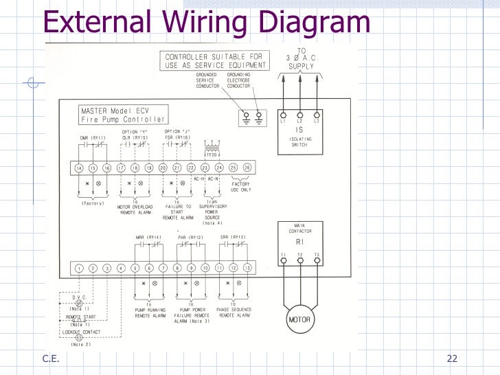
Varaible Speed Drives For Motor Driven Fire Pumps

18 Pulse Drive With 3 Transformers 11 Download Scientific Diagram


