Micro Blue Pump Wiring Diagram
If this is the case wire according to the M-Series diagram. Identify which is present and wire according to the diagram below.

Wiring Diagram Ac Cassette Panasonic
Hydraulic leak in either the 690 System or service brake system.

Micro blue pump wiring diagram. Current P-Series indoor units will have either a CN4F or CN31 drain safety connector. The MicroBlue is also UL plenum rated and backed by BlueDiamonds standard market leading three year warranty. Old style micro switches use a black wire see 8B diagram on page 2.
Panels are also available See wiring diagram. 7 way trailer wiring diagram represents wire location and color but is not supplied to represent any wire or color functions. The actuator is not functioning properly.
If this is the case wire according to the M-series diagram. Power cord on all Zoeller Grinder Pumps contains a green conductor for grounding to help. G L2 L1 NC COM ND 1 2 3 4 1 2 3 Pump Connections 05A.
In this short video I cover how to wire up a 12v Micro switch tap and 12v submersible water pump with links below for the items. Zoeller pump wiring diagram - Electrical Supplies question. Always refer to your thermostat or equipment.
Configuration and use manual mmi 20019043 rev ab march 2018 micro motion model 2700 transmitters with analog outputs configuration and use manual. Inspect all tubing and connectors for leaks and tighten or replace as neces sary. This diagram is to be used as reference for the low voltage control wiring of your heating and AC system.
Switch the 690 System to the on position. On the ratchet relay 3 located in the gray Geo-Loop electric box and two blue wires 5 going to the micro switches on the grout cylinders. Make sure the pump electrical supply circuit is equipped with fuses or circuit breakers of proper capacity.
3 Ratchet relay com 1 Black 14 gauge power supply from grout pump fuse Red wire. Check for proper connection of the blue and green wires. Wiring diagram blue brown.
Cn 3 fan-l fmotor l e w hi te blue tsensor cn 4 micro switch transformer cn 1 cn 2 bl ue fu se yellow control board cn 1 n n1 n2 bl ue wh it e capacitor red 115v60hz n compressor re d white olp blue capacitor t31 5a l1 25 v hsensor cn 7 bl ac k brown blue cn 8 cn 2 cn 6 fan-h p6p7 d6951-900 - 8 - schematic. Schematic wiring diagram no co m. The other thing that you will come across a circuit diagram could be lines.
Micro Motion Wiring Diagram. There are two things that will be present in any Shurflo Water Pump Wiring Diagram. Older models may not have one of these connectors.
59 x 146 x 157. Three Phase Wiring Diagram. A wiring diagram is a kind of schematic which makes use of abstract pictorial signs to reveal all the affiliations of components in a system.
Current P-Series indoor units will either have a CN4F or CN31 drain safety connector. The wiring for the 12v micr. Externally Powered Discrete Input Wiring 2.
Toggle switch load side 1 Red 14 gauge wire power supply from grout fuse 5 From grout pump auto single pole single throw Note. Please contact your trailer manufacturer for further details. Brown powerpositive blue groundneutralnegative black output.
Refer to wiring diagram on page 6. If your truck has a built in 7 pin socket but you only need 5 of the pins. A circuit is generally composed by many components.
Slim volt M-Series Non-inverter models - Maxi Blue Pump. The MicroBlue is a dual voltage pump which uses proven thermistor level sensing technology to remove the risk of stuck or sunken float switches. 5 From grout pump auto single pole single throw toggle switch load side Note.
Figure 2 6 Water Pump Wiring Diagram Figure 6 Water Pump Wiring Diagram How To Use A Submersible Water Pump 24 Volt Wiring Diagram 948bb Well Pump Wiring Schematic Digital Resources Wiring Diagram Needed For Water Pump Elec Fan Line Loc Hardcore Grundfos Sqflex Solar Water Pump Wiring Diagram. Typical pump wiring diagrams. Main fuse 30 amp Blue wire.
On the ratchet relay 3 located in the gray Geo-Loop electric box and two blue wires 5 going to the micro switches on the grout cylinders. The pump power cable. Central States Bus Sales technical support team is happy to assist you in finding a wiring diagram for your bus or helping to diagnose your Blue Bird bus electrical system.
What wire goes where. Older models may not have one of these connectors. Identify which is present and wire according to the diagram below.
Connect the negative wire from the pump to the ground wire from your negative busbar or chasis. Old style micro switches use a black wire see 8B diagram on page 2. Connect your live feed from the battery to the positive wire from the tap they should be labelled Step 2.
If a Zoeller control. Mounting and sensor wiring for 9 wire remote installations figure 4 2. Connect your negative wire from the tap to the positive wire of the pump.
The first component is symbol that indicate electrical element from the circuit.

Pin On Wiring Diagram

Graphic Volvo Wiring Diagram Alternator Wiring Diagram
Plc Wiring Diagram Download Scientific Diagram
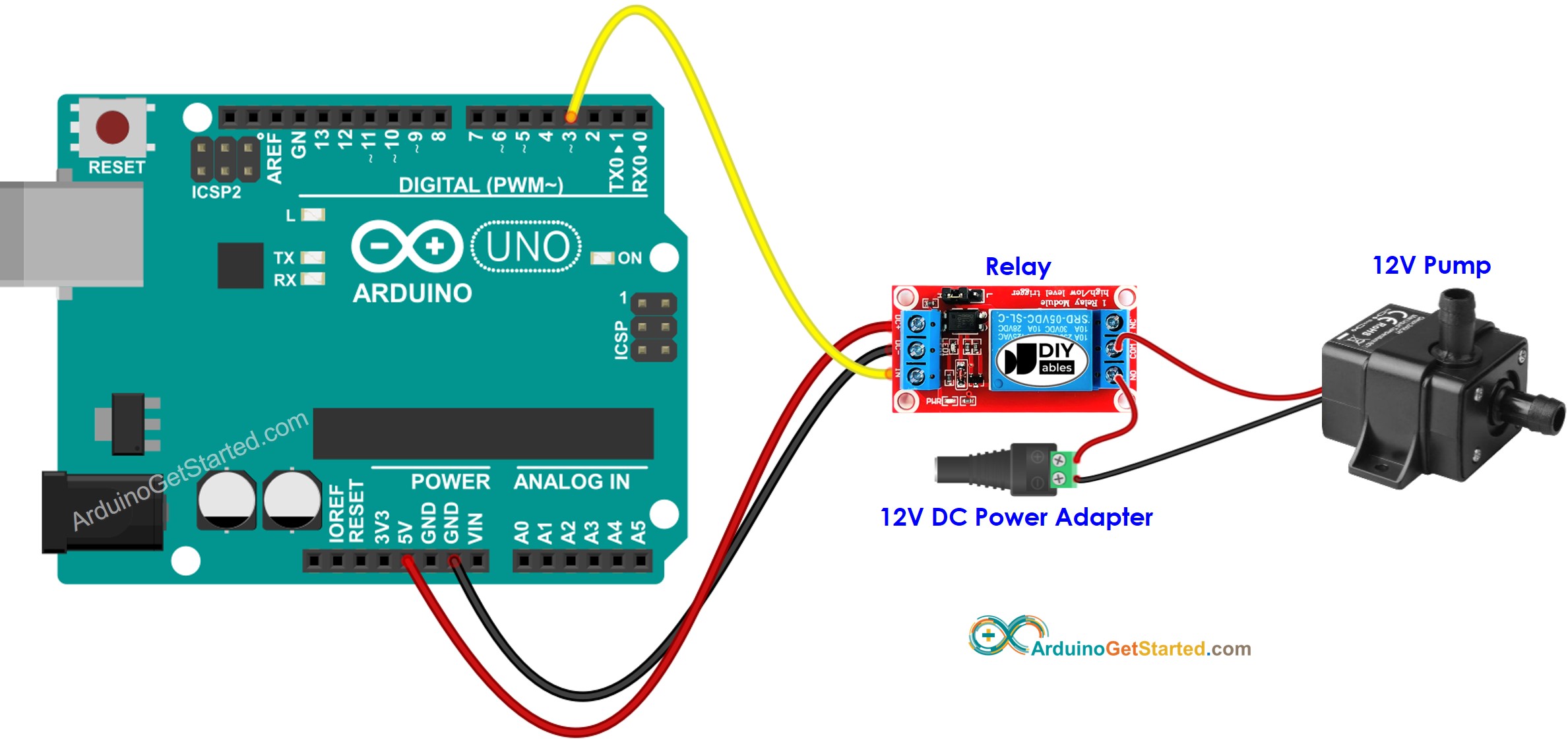
Arduino Controls Pump Arduino Tutorial

New Honeywell Thermostat Th4110d1007 Wiring Diagram Diagram Diagramsample Diagramtemplate Wiringdiagram Di In 2021 Thermostat Wiring Thermostat Smart Thermostats

White Motion Sensor Wiring Diagram Sample Motive Ideas Lighting Decoration Themes Adjustable Electronic Gif Resize D336 2 Motion Detector Wiring Diagram Sensor

Basic Hvac Wiring Diagrams Schematics At Diagram Pdf Wiring Diagram Diagram Diagram Design

Wiring Diagram Showing The Graphical Code For Instrument Control And Download Scientific Diagram

Pin On Electricidad Y Electronica

Diagram Of Spitronics Pluto M20 In 2021 Diagram Ecu Saturn

5 Pin Wiring Diagram Electrical Diagram Electrical Circuit Diagram Wiring Diagram

Lewmar Windlass Wiring Diagram Upgrade Windlass Power Wiring Of Lewmar Windlass Wiring Diagram With Windlass Wiring Diagram F Wiring Diagram Power Wire Diagram

Wiring Diagram For Daylight Running Lights

23 Second Animation Wiring Diagram Wiring Diagram Automotive Technician Diagnostic Tool

09132211861 Circuit Diagram Control Board Wiring Power Electrical Wiring Rl1 Relay

Kamar Dinding Bertema Kartun Chil97 Tips Trik Computer Keyboard Shortcuts Vga Vga To Hdmi
Wiring Diagram Of Fire Pump Diesel Engine Machines Mechanical Engineering


18 Electric Mobility Rascal 255 Wiring Diagram Wiring Diagram Wiringg Net Diagram Wiring Diagram Rascal Scooter

Nissan X Trail Wiring Diagram Car Engine Diagrams Nissan Xtrail Nissan Wiring Diagram